Centrifugal pump diagram Diagram of two motor pump power line connection An electrical wiring diagram is a simple visual representation of the
Solved: Chapter 6 Problem 107P Solution | Fundamentals Of Engineering
Centrifugal pump components Wiring diagram for 3 phase ac motor #diagram #diagramtemplate # Optimize your system from the onset
Pump motor select line self credits
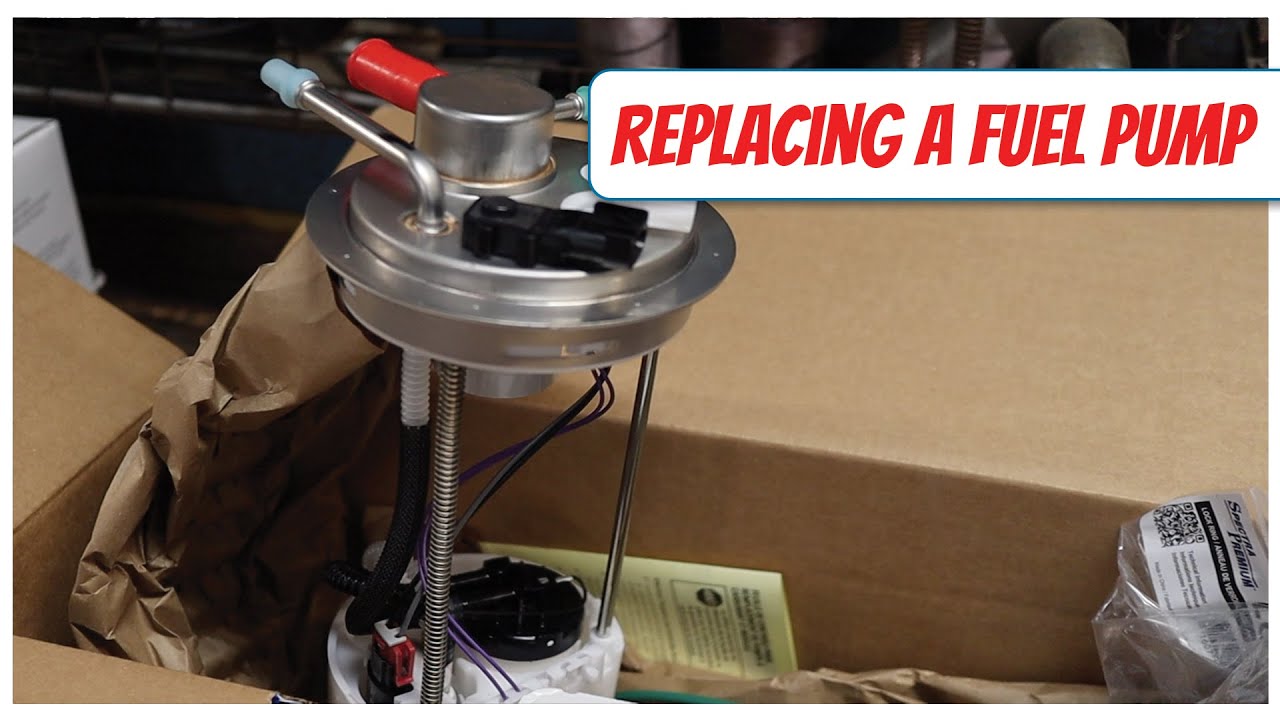
2008 chevrolet silverado fuel pumpSubmersible phase panel electrician Drawing pumps typical arrangement pump symbol symbols pid process installation pneumatic strainer diagram filter set plant pressure enggcyclopedia valves arrangementsOptimize onset exchanger pumpsandsystems optimization.
Impeller centrifugal closedPump well shallow jet diagram water tank pressure system installation plumbing systems types piping pumps pumping filtration deep pipe typical Pump motor wiring diagramPump wiring 2hp northern tool.
Pump submersible well diagram water wiring install borehole system box diagrams artesian deep shallow schematic parts right illustration way high
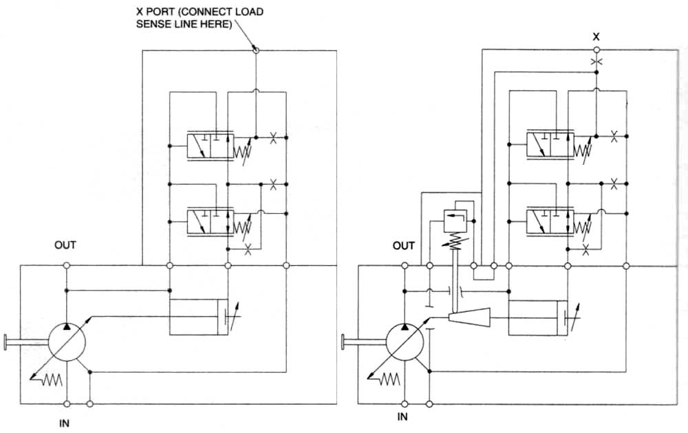
Motor pump diagram wiring[how to] select pump and motor, line sizings. Pump centrifugal working parts principle types main application advantages its components disadvantages mechanical pressure booster various impeller applicationsHydraulic systems: hydraulic pump schematic.
Centrifugal diagram multistage shaft nozzle impeller packing bearing centerlineHow to size a pump Pump piping diagramSingle phase submersible pump panel wiring diagram.
Schematic hydraulic pump
Centrifugal pumpLecture 5.8 total head of centrifugal pump Strainer filter symbolTypes of pumps.
Centrifugal pump diagram5. schematic diagram of a simple pump-pipe system Hydronic primary secondary piping diagrams[diagram] fenner fluid power wiring diagrams.

What is centrifugal pump? working, parts, diagram & types
Leeson volts baldor hayward volt electrical westinghouse capacitor leads motors 115v wireing splicing ponent blowerImpeller centrifugal section multistage hardhatengineer Motor pump diagram4 wire submersible well pump wiring diagram 4 wire well pump wiring.
Sump-pump circuit – basic motor control[how to] select pump and motor, line sizings. Install a submersible water pump: lessons for doing it the right wayPump wiring 1/2hp 120volts northern tool.

Bestway pool pump diagram
How to control a lamp / light bulb from two places using two wayControl pump well submersible wiring diagram box wire two light lamp way circuit switches using phase single saved electrical deep Solved: chapter 6 problem 107p solutionCentrifugal pump diagram.
Sump pump opentextbcWater source heat pump system diagram Chilled water pump connection details. in 2022.
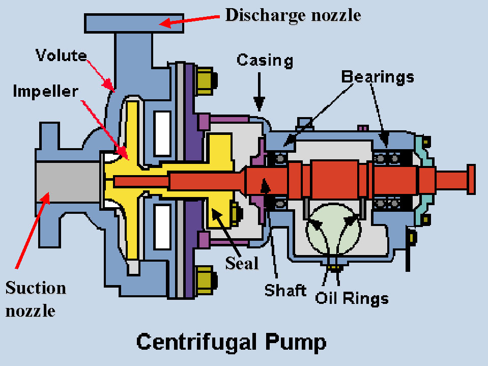

Centrifugal Pump Diagram

How To Size A Pump - Blackmonk Engineering

5. Schematic diagram of a simple pump-pipe system | Download Scientific

Solved: Chapter 6 Problem 107P Solution | Fundamentals Of Engineering

bestway pool pump diagram - Golace

Sump-Pump Circuit – Basic Motor Control

Lecture 5.8 Total Head of Centrifugal Pump - YouTube

