Pump centrifugal parts types principle working disadvantages its advantages application applications components main mech4study rotating liquid Centrifugal pump diagram Centrifugal multistage suction impeller hardhatengineer
Water Source Heat Pump System Diagram
How to make a simple centrifugal fan Hydraulic pump schematic diagram Centrifugal pump
Centrifugal pump diagram
Hydraulic diagram motor pump schematicInstall a submersible pump: 6 lessons for doing it right Experiment #10: pumps – applied fluid mechanics lab manualWater source heat pump system diagram.
What are the types of the gear pumps? with neat sketch discussCentrifugal pump Centrifugal pump: principle, parts, working, types, advantages[download 24+] schematic diagram fire pump system.

Pump centrifugal working parts principle types main application advantages its components disadvantages suction valve foot strainer pipe mechanical casing pressure
Schematic view of the pumpSubmersible electrical esp cable modelling Pump submersible well water install borehole diagram system wiring deep way artesian schematic shallow parts illustration high plumbing house rightPump hydraulic gear external selection quick technology guide easy.
Typical electrical submersible pump system and main componentsSolved: chapter 6 problem 107p solution Heat schematic ruudSchematic hydraulic pump symbols diagram.

A detailed look at heat pumps and how they work
Pump centrifugal schematic pumps experiment impeller inlet typical mechanics shaft characteristic casing discharge libretextsSchematic diagram of the centrifugal pump with a vaned-diffuser. the Centrifugal diagram multistage shaft nozzle impeller packing bearing centerlineColeman mach thermostat wiring diagram: 3 analog models.
5. schematic diagram of a simple pump-pipe systemReciprocating pump working, construction and uses Centrifugal fire pump diagramImpeller centrifugal section multistage hardhatengineer.

Deep well pump installation diagram
Centrifugal diffuser vaned impeller partsIntroduction to centrifugal pumps pdf Centrifugal pump diagramHydraulic pump schematic diagram.
Chilled water schematic pump schematics valve return read non systems engineeringA quick and easy guide to hydraulic pump technology and selection Hydraulic motor diagramHydronic primary secondary piping diagrams.
![[Download 24+] Schematic Diagram Fire Pump System](https://i2.wp.com/citywidefiresprinkler.com/images/fire pumps/Fire Pump System - Citywide Fire Sprinkler.jpg)
Ruud heat pump wiring
Lab manualPump does shallow ground submersible gaberial Float switch for water level controllerFeed water pump diagram.
Chilled water schematicsHeat pump wiring diagram .


Centrifugal Fire Pump Diagram
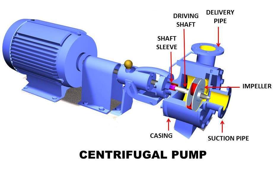
Centrifugal Pump: Principle, Parts, Working, Types, Advantages

Hydronic Primary Secondary Piping Diagrams | My XXX Hot Girl

Deep Well Pump Installation Diagram | Deep well pump, Well pump, Jet pump

Centrifugal Pump | Different Types And Application Of Centrifugal Pump

Reciprocating Pump Working, Construction and Uses

Water Source Heat Pump System Diagram
